Introduction to Lidar of In-vehicle Sensors 2023
 Published: Apr 26, 2023
Contents
LIDAR is mainly used in autonomous driving applications to detect information about obstacles on the road, transmit data and signals to the brain of autonomous driving, and then make corresponding driving actions. However, common outdoor interference factors such as rain, fog, snow, dust, high and low temperatures have a great impact on LIDAR recognition.
Therefore, LIDAR needs to be tested extensively in special environments such as rain, fog, light and dust before it is put into practical application. Under natural environmental conditions, the required test scenes are unavailable and cannot be reproduced, which cannot meet the demand for a large number of real environment tests of LIDAR.
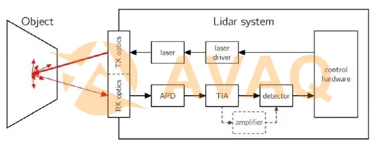
I. Structure of LIDAR
The key components of LIDAR include control hardware DSP (digital signal processor), laser driver, laser emitting light emitting diode, emitting optical lens, receiving optical lens, APD (avalanche optical diode), TIA (variable transconductance amplifier) and detector according to the signal chain of signal processing, as shown below. Among them, all are electronic components except for the transmitting and receiving optics. With the rapid evolution of semiconductor technology, the performance has gradually improved while the cost has rapidly decreased. However, optical components and rotating machinery account for most of the cost of LIDAR.
Ⅱ. Types of LIDAR
There are different types of LIDAR on the market, which can be divided into mechanical, MEMS, phased array, and flooded surface array (FLASH) according to the driving method.
Mechanical type
Take Velodyne's 64-line radar launched in 2007 as an example. It stacks 64 lasers vertically and rotates them at 20rpm. The simple understanding is to turn laser points into lines by rotation, and transform the lines into surfaces by stacking 64 lines to get point cloud data to obtain 3D environment information.
The mechanical structure requires complex mechanics, while the point cloud measurement requires precise positioning of the installation. Considering the influence of environment and aging, the average failure time is only 1000-3000 hours, which is difficult to meet the minimum 13000 hours requirement of vehicle manufacturers. And because LiDAR is installed on the roof of the car, the civilian sector needs to consider the problems of external maintenance, such as the impact of car washing. Therefore, the mechanical structure greatly limits the cost and application promotion.
MEMS
MEMS LiDAR uses the technology of micro-electro-mechanical system to drive the rotating mirror and reflect the laser beam to point in different directions.
The advantages of solid-state LIDAR include: fast data acquisition, high resolution, strong adaptability to temperature and vibration; through beam control, detection points (point clouds) can be distributed arbitrarily, for example, in the highway mainly scan the front far, for side scan but not completely ignored, at intersections to enhance the side scan. Mechanical LIDAR, which can only rotate at a uniform speed, cannot perform such fine operations.
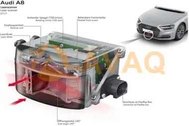
Typical applications are Valeo SCALA LIDAR. It is currently used in the Audi A8 (the first L3 level self-driving vehicle). It is installed in the front bumper position and uses MEMS technology to obtain a scanning angle of 145° and a detection distance of 80m.
Phased array (OPA)
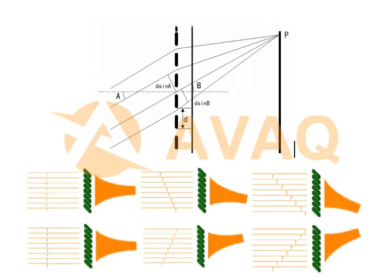
Principle of optical phased array radar: it mainly uses the principle of interference of light. The position of the central bright pattern (main flap) after grating diffraction can be changed by changing the phase difference of the incident light in different slits, as shown in the figure below.
Advantages and disadvantages of phased array (OPA)
Advantages:
- ①Simple structure and small size: Since no rotating parts are needed, the structure and size of the radar can be greatly compressed to improve the service life and reduce the cost.
- ②Simple calibration: mechanical LIDAR often needs precise adjustment of its position and angle due to fixed optical structure and adaptation to different vehicles, while solid-state LIDAR can be adjusted by software, which greatly reduces the difficulty of calibration.
- ③Fast scanning speed: Without being limited by the speed and accuracy of mechanical rotation, the scanning speed of optical phased arrays depends on the electronic properties of the materials used and can generally reach MHz magnitude.
- ④High scanning accuracy: The scanning accuracy of optical phased array depends on the accuracy of the control electric signal, which can reach the order of one thousandth of a degree or more.
- ⑤Good controllability: The beam pointing of optical phased array is completely controlled by the electric signal, which can be arbitrarily pointed within the allowed angle range and can be scanned in the key area with high density.
- ⑥Multi-target monitoring: a phased array can be divided into multiple small modules, each module can be controlled separately to lock and monitor multiple targets at the same time.
Disadvantages:
- ① limited scanning angle: adjusting the phase at most can only let the central bright pattern change about ± 60 °, the actual do 360 ° acquisition then generally need 6.
- ② side flap problem: grating diffraction in addition to the central bright pattern will also form other bright patterns, this problem will allow the laser in the direction of maximum power outside the formation of side flap, dispersion of laser energy.
- ③High processing difficulty: optical phased array requires the array unit size must not be larger than half a wavelength, generally the current working wavelength of LIDAR are in about 1 micron, so the size of the array unit must not be larger than 500nm. and the higher the array density, the more concentrated the energy, which has improved the requirements of processing accuracy, requiring a certain technical breakthrough.
- ④Large receiving surface and poor signal-to-noise ratio: Traditional mechanical radar only needs a small receiving window, but solid-state lidar needs a whole receiving surface, so it will introduce more ambient light noise and increase the difficulty of scanning resolution.
Flooded light surface array type (FLASH)
The principle of flooded-light surface array type is similar to TOF camera, that is, fast flash, which does not go for scanning like MEMS or OPA solutions, but directly emits a large area of laser light covering the detection area for a short time, and then uses a highly sensitive receiver to complete the drawing of images around the environment. It operates more like a camera. The laser beam will diffuse directly in all directions, so it only takes one quick flash to illuminate the entire scene. The system then uses an array of miniature sensors to capture the laser beams reflected back in different directions.
One of the major advantages of Flash LiDAR is that it can record the whole scene quickly, avoiding all kinds of troubles caused by the movement of the target or LiDAR during scanning. There are 2 current development directions, one is the single photon counting type of Geiger mode APD to generate digital images directly on photon counting; the other is the traditional CMOS light intensity simulation acquisition to get intensity map, and convert the intensity map into distance information.
Ⅲ. The Data Transmission of LIDAR
LIDAR, due to the large amount of data, the current control architecture basically uses the raw data of each light point to send back to the central controller for processing, so it usually uses such high-bandwidth networks as FlexRay or Ethernet for communication. For example, Valeo's SCALA used Flexray in the 1st generation and started using Ethernet in the 2nd generation.
LiDAR usually supports timing from the hardware level, and usually provides support for three kinds of time synchronization interfaces.
1) IEEE 15882008 synchronization, which follows a precise time protocol and enables precise clock synchronization for measurements and system control via Ethernet.
2) Pulse Synchronization (PPS), which synchronizes data via synchronization signal lines.
3) GPS synchronization (PPS+UTC), data synchronization is achieved through synchronization signal line and UTC time (GPS time).
Take the data of the most popular rotating LiDAR as an example, the data is 10hz, that is, LiDAR turns once in 0.1s time, and the data obtained by hardware is cut into different packets according to different angles, and each packet contains the data of all points in the current sector, including the timestamp of each point, xyz data of each point, emission intensity of each point, each point The laser transmitter id from which each point originates, and other information. For example, the latest Livox Horizon LIDAR also contains multi-echo information and noise information.
Next Industry Focus
Different Types of Ceramic Capacitors
 Update Time: Apr 26, 2023 Consumer Electronics
 Popular Industry Focus
Hot Products
-
![OPA2277U/2K5]()
OPA2277U/2K5
Texas Instruments
Operational Amplifier General Purpose with 1MHz Bandwidth in 8-SOIC Package
-
![ADS7864Y]()
ADS7864Y
TI
This -bit ADC chip from TI offers high-precision conversions and efficient power management for various application
-
![UCC28019ADR]()
UCC28019ADR
Texas Instruments
Achieve precise DC-DC conversion with the UCCDR, a reliable PWM controller for power supplies
-
![TPS54427DDAR]()
TPS54427DDAR
Texas Instruments
PMIC IC that functions as a DC/DC converter with an input voltage range of 4
-
![BQ24123RHLR]()
BQ24123RHLR
TI
Enhanced electromagnetic interference (EMI) performance for reliable operation
-
![TPS630701RNMR]()
TPS630701RNMR
Texas Instruments
The TPS630701RNMR is a DC-DC Converter in VQFN-15-HR(2.5x3) packaging, meeting ROHS standards


Related Parts

Featured Manufacturers